As is always the way with me, I ended up spending an inordinate amount of time procrastinating over whether or not we needed to add additional electrics to the car. Our needs are pretty basic:
- 12V to power our fridge
- 240V to power our laptop and AA battery charger (probably via a 300W pure sine inverter)
- 2 or 3 5V USB outlets for phones, GPS, etc
I tried pretty hard to convince myself that we could get by using the main car battery to power all of this lot, but in the end I couldn’t shake the vision of settling down with the laptop for the evening and accidentally leaving it on only to find us with a flat battery the next morning; unable to start the car; on a deserted steppe in Mongolia. We would be literally f*#k*d.
So we needed a second battery, and all the paraphernalia that comes with it…..
To avoid my nightmare scenario, the second battery needed to be electrically isolated from the main battery at all times other than when the engine is running and the alternator is generating enough juice to charge both batteries. There’s a few ways to do this:
- A high amperage switch
- Voltage sensing relay
- Electronically controlled solenoid/relay
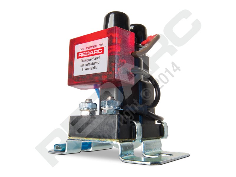
Using a big switch to control the connection of the two batteries appealed due to the simplicity and reliability, but at the end of the day didn’t solve the real problem that us simple-minded humans don’t always remember to do what we’re supposed to do and at some point we were eventually going to leave the switch on and drain the main battery. The voltage sensing relay requires ‘semi-invasive’ wiring to install, which didn’t appeal. So that left the electronically controlled solenoid/relay. After much deliberation, I ended up buying a Redarc SBI12 for no reason other than people were pretty positive about it online and there were reasonable postage options available to Japan.
Given I already knew what I wanted to power using the second battery, ‘designing’ the rest of the circuit was mostly a case of making sure that my cables were adequately sized to ensure the voltage drop over their lengths was within 2%. The maths for this is fairly straightforward:
Vd = 0.02 x 12V = 0.24V
where; Vd = 2% permitted voltage drop at 12V
A = (len x I x 0.017) / Vd
where; A = cross sectional area (mm2); len = cable length (m); I = expected current (A)
These same equations are quoted all over the ‘net, but I liked the PDF they have at Redarc.
For example, the cable that will run from the battery at the front to the fuse box under our bed…. I overestimated a length of 3m and a max current draw of 39.3A which gave me a required cross sectional area of (3 x 39.3 x 0.017) / 0.24 = 8.3mm2 to ensure I only drop 2% of the voltage over it’s length. Each result I rounded up to the next available cable size, so in this case 10mm2.
The one surprise was that I calculated our inverter could draw up to 27A if we were maxing it out, so I had to factor in a 70A relay to switch the power to it rather than rely on a simple 20A switch.
Here’s the ‘final’ circuit (which I originally drew in the free trial of Omnigraffle but had to export via some web thingy as my free trial had expired so it looks a bit broken)
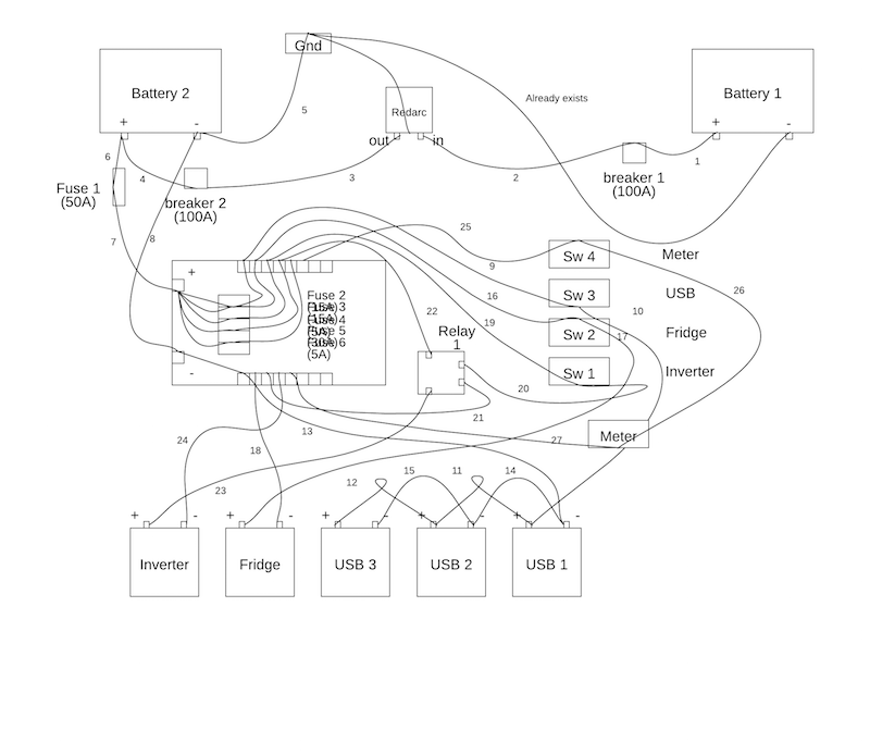
From here I was able to work through each cable and decide what terminations were required, and, finally, with all of that information I was able to generate a big shopping list of items.
This exciting tale continues in part 2.
Vd = 0.02 x 12V = 0.24V
where; Vd = 2% permitted voltage drop at 12V
A = (len x I x 0.017) / Vd
…My thoughts exactly.
I’m glad you’re in agreement!